Wednesday, August 24, 2011

Salam Aidilfitri....Maaf zahir & Batin


Asslamualaikum & Salam sejahtera....

Dikesempatan ini saya ingin mengucapkan Selamat Hari Raya Aidilfitri kepada semua Pelajar SPS 4A...Semoga lebaran kali ini memberikan kebahagiaan & kesempatan untuk kita bermaaf-maafan dgn ibu bapa, keluarga & sahabat handai....Yang paling utama ialah menjaga diri anda semua semoga sentiasa berada dalam keaadan selamat dan dilingdungi oleh-Nya...
Ingin saya berpesan, sentiasalah menjaga adab pergaulan dan tidak melakukan perkara-perkara yang boleh mendatangkan dosa kecil & dosa besar....Insyaallah semoga kita semua diberkati & diredhai oleh Allah SWT....
Kelas kita akan disambung semula pada Hari Rabu 7 September 2011...Saya mohon ampun & maaf jika ada salah silap sepanjang saya mengajar anda semua.....

.........SELAMAT HARI RAYA AIDILFITRI.......

Monday, August 15, 2011

Extrude

The EXTRUDE command allows you to create a solid object from circles, polygons, and objects, created from or converted to Polylines, that have "closed" paths. You can extrude planar faces along a path, or you can specify a height value and a tapered angle. Each face has a positive side, which is the side in the direction of the face's normal (the current face you're working on). Entering a positive value extrudes the face in its positive direction (usually outward); a negative value extrudes in the negative direction (usually inward).

sebelum EXTRUDE

Sunday, August 14, 2011

Projek Mini Bar


Create A Revolved Solid

With REVOLVE, you can create a solid by revolving a closed object about the X or Y axis of the current UCS, using a specified angle. You can also revolve the object about a line, polyline, or two specified points. Similar to EXTRUDE, REVOLVE is useful for objects that contain fillets or other details that would otherwise be difficult to reproduce in a common profile. If you create a profile using lines or arcs that meet a polyline, use the PEDIT Join option to convert them to a single polyline object before you use REVOLVE.

You can use REVOLVE on closed objects such as polylines, polygons, rectangles, circles, ellipses, and regions. You cannot use REVOLVE on 3D objects, objects contained within a block, polylines that have crossing or intersecting segments, or polylines that are not closed.


Thursday, August 4, 2011

WIRE FRAME MODEL

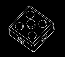
A wire frame model is a visual presentation of a three dimensional or physical object used in 3D computer graphics. It is created by specifying each edge of the physical object where two mathematically continuous smooth surfaces meet, or by connecting an object's constituent vertices using straight lines or curves. The object is projected onto the computer screen by drawing lines at the location of each edge.

Using a wire frame model allows visualization of the underlying design structure of a 3D model. Traditional 2-dimensional views and drawings can be created by appropriate rotation of the object and selection of hidden line removal via cutting planes.

File:Wire frame.svg
Contoh Wireframe model

File:Obj lineremoval.png
Objek Wireframe tidak bergarisan tersembunyi

Wednesday, August 3, 2011

Kuiz 1

Assalamualaikum & salam sejahtera....

Kuiz 1 akan dilaksanakan pada 7 Ogos 2011 (Ahad). Antara tajuk atau topik yang berkaitan ialah paparan autocad (namakan), kawalan pandangan 3D (kepentingan), viewports & viewpoints (perbezaan), arahan-arahan modify 3d (singkatan) dan tab command & toolbars pada tetingkap Customize (fungsi). Diharapkan semua pelajar bersedia dengan mencari bahan-bahan bacaan di atas talian atau buku nota.

Selamat Menjawab.

3D Dengan Arahan 'Thickness'

Asslamualaikum & Salam Sejahtera....

Selain menggunakan kaedah 'wireframe' untuk melukis objek 3D, kita juga boleh menggunakan arahan 'Thickness' dalam melukis objek 3D melalui perisian AutoCad. Kaedah arahan 'Thickness' ialah menggunakan atau memanipulasikan ketebalan garisan untuk membentuk objek 3D. Dengan kata lain, kita memberikan ketebalan pada garisan untuk menampakkan bentuk objek dalam 3D.


'Thickness' boleh dilakukan dalam pelbagai paksi, samada paksi Y, X ataupun Z. Jika 'Thickness' garisan atau objek adalah sifar (0), ia tidak akan memberikan kita objek 3D. Jika kita letakkan nilai 'Thickness' adalah negatif, tebal garisan tersebut akan dinaikkan mengikut arah bertentangan. Sebagai contoh, kamu meletakkan nilai -3 pada 'Thickness' garisan pada paksi Z ia akan memberikan tebal garisan tersebut ke bawah sebanyak 3 unit.

Jenis-jenis objek/garisan yang boleh digunakan untuk 'Thickness' adalah 2D solid, Arcs, Circles, Lines, Polylines (including spline-fit polylines, rectangles, polygons, boundaries, and donuts), Text (only if created as a single-line text object using an SHX font), Traces & Points.

To set the 3D thickness of new objects
  1. Click Format menu Thickness.
  2. At the Command prompt, enter the value for the thickness distance.

    When new objects are created, they have the specified 3D thickness.

To change the 3D thickness of existing objects
  1. Select the objects whose 3D thickness you want to change.
  2. Right-click one of the objects. Click Properties.
  3. In the Properties palette, select Thickness and enter a new value.

    The selected objects change to display the specified 3D thickness.